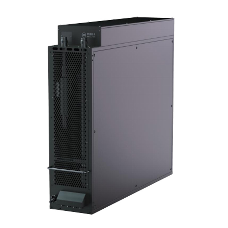
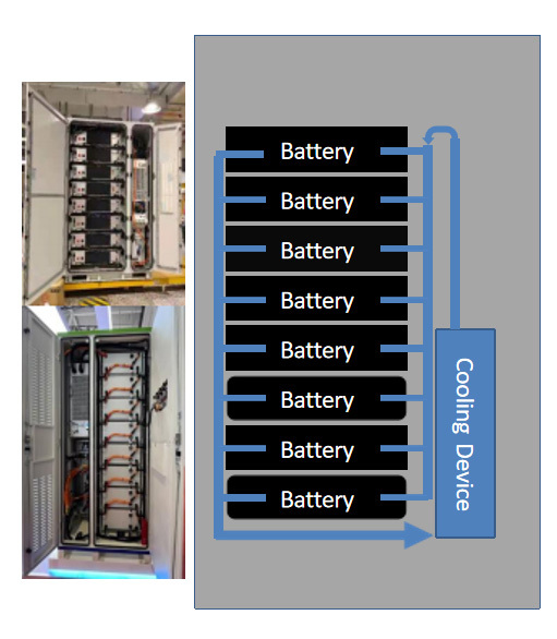
Single cabinet (industrial and commercial storage) energy storage thermal management architecture
-
25±15℃
-
8 Pack
-
30 or 52Cells/Pack
-
LFP 3.2V
-
280AH
-
0.5C @ 4.5kW
-
0.75C @ 8kW
-
215-416kWh
-
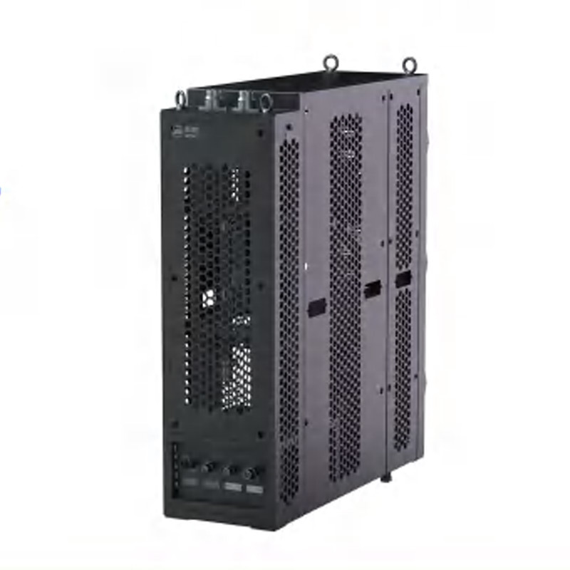
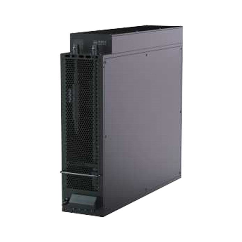
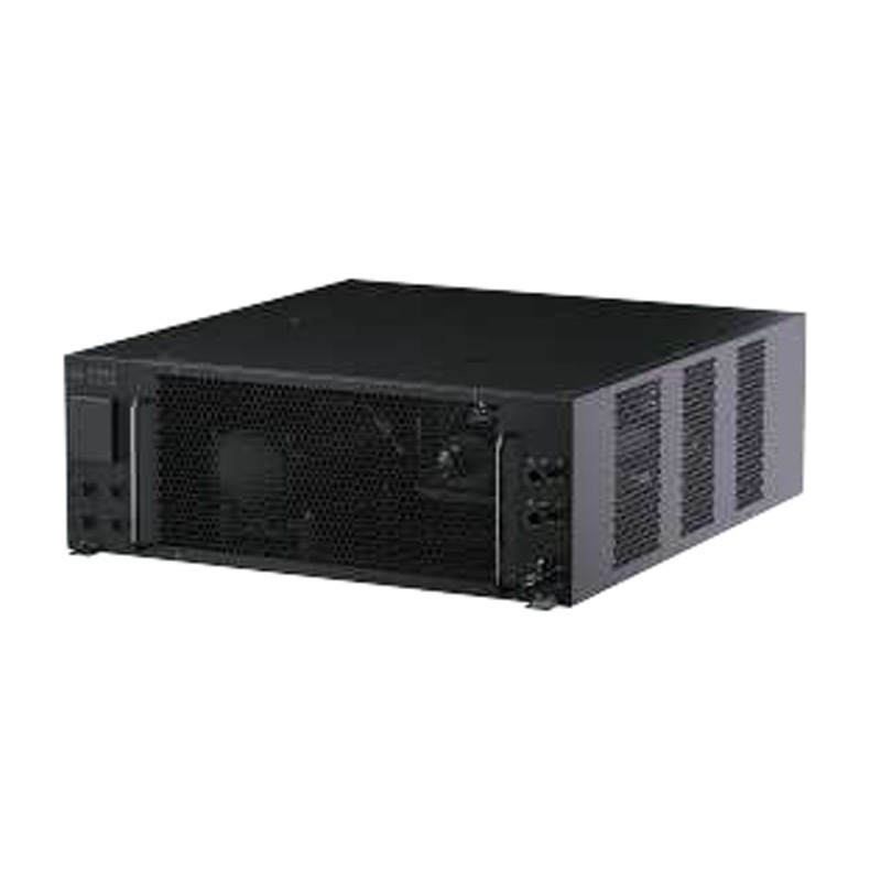
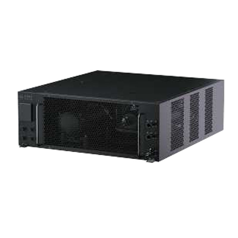
The 4.5-8kW water-cooled unit adopts modular customization and standardized platform;
-
The water cooler meets the heat exchange requirements for charging and discharging energy storage cabinets at 0.5C to 0.75C, covering the vast majority of operating conditions;
-
The chiller unit has a compact structure, is easy to install, and has strong adaptability;
-
The system can be equipped with an intelligent maintenance kit to accurately calculate maintenance requirements;
-
The air temperature of the whole machine is automatically selected based on the ambient temperature and battery cell temperature, and the air conditioning and environmental cooling modes are selected to improve system energy efficiency;
-
The whole machine is easy to connect and has high consistency in the quick plug structure;
-
Optional remote management system, real-time monitoring of the operation status of multiple machine cabinets;
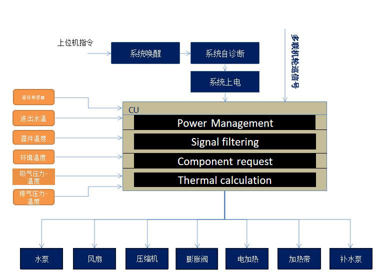
Energy storage thermal management control
The control system collects pressure and temperature information from sensors to control the working speed, position, and current of the actuator, ensuring that the battery operates at the optimal temperature. At the same time, the system includes improved self diagnosis and fault operation modes to ensure the normal operation of the system and prevent system failure
-
High ambient temperature and battery temperature exceeding threshold temperature:
Request the air conditioning system to work and meet the cooling needs of the battery;
-
The ambient temperature is not high and the battery temperature has not exceeded the threshold temperature:
The water pump works by dissipating heat through pipelines
-
The ambient temperature is not high and the battery temperature exceeds the threshold:
The water pump is working, and the solenoid valve control circuit is switched to the radiator working circuit
-
The energy storage system stops working and the battery temperature does not exceed the threshold:
The thermal management system stops working
-
The energy storage system stops working and the battery temperature exceeds the threshold:
The thermal management system delays operation until the battery temperature reaches the threshold
Schematic diagram of energy storage thermal management

Schematic diagram of 8kW energy storage thermal management system
-
The system mainly includes compressors, condensers, plate heat exchangers, circulating water pumps, low-temperature radiators, electronic fans, etc.
-
The system uses electronic three-way valves to divide the battery cooling circuit into air conditioning cooling and natural forced air cooling modes, which can effectively reduce the energy consumption of battery cooling in low-temperature environments and improve system efficiency.
-
Equal path circuit design, more uniform distribution of battery cluster flow, small temperature difference between battery cells, and long battery life.
-
Flat platform design with strong scalability, adjusting device selection to meet different discharge rates and scales of energy storage and heat exchange requirements.
-
The system adopts fast plug, high module level, easy installation, and high product quality consistency.
Thermal management simulation
Platform based simulation model
The 1D fluid simulation model is used to calculate the flow distribution and heat transfer performance of the system circuit, determine the difference between the flow rate and heat transfer capacity of the liquid cooling circuit and the target, verify the rationality of the selection, improve development efficiency, and reduce development costs. The model can be extended to multiple battery clusters and water temperature management.

Flow allocation and heat transfer performance simulation model (single cluster)
The simulation system includes:
- Maximum system flow
-
System pressure distribution
-
Flow resistance characteristics
-
Flow distribution of battery circuit
-
Heat transfer performance
8kW energy storage structure

Integrated liquid cooling unit
The unit integrates components such as fans, compressors, water pumps, plate exchangers, electric heating, and electrical control, with high integration and high space utilization.
For maintenance and after-sales service, single-sided disassembly and assembly of the system allows for comprehensive inspection and maintenance of the entire machine
System components:
High strength plate heat exchangers, microchannel parallel flow heat exchangers, and DC high head water pumps effectively reduce system weight and improve system reliability.
The import and export pressure detection function can provide early warning and prevent system failures caused by water shortage.


